Engine Installation on "Buddy Boy"

The following progression leads you through the installation of the 315hp Yanmar 6LYs on "Buddy Boy"...
As is usually the case, clicking on an image will carry you to a larger version...
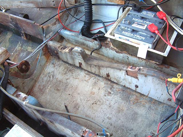
Typically, this the scene you'll see at the beginning of a repower on an original installation Bertram 31. So the first job is to get rid of the old beds and spiff up the spaces.
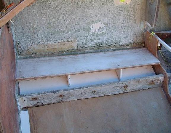
After ripping out the old bed sisters, the spaces are degreased, soap and water scrubbed, dried, and wiped liberally with denatured alcohol. At this point, I fitted gelcoated sheets of fiberglass to the hull between the stringers and outboard below where the shelves will be. The image above shows the shelves in place, but before cutting the outboard stringer to the angle required for the engines.
The following diagram shows the cross section of how the beds are constructed and the aluminum ramp configuration:

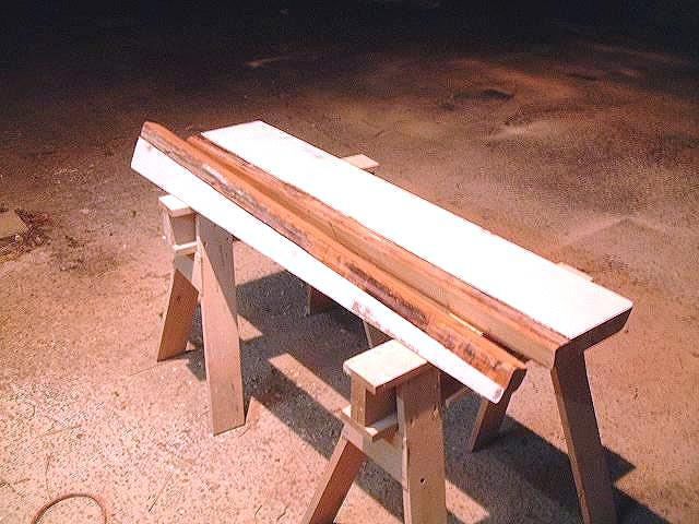
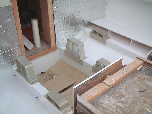
Below is a pair of the new sisters ready for installation. The construction is of solid hard wood and laminated with gelcoated fiberglass sheet on the inboard sides. The outboard sister has been angled and the inboard sister is the same height as the inboard stringer, Both have been angle cut at the bottom to correspond to the dead rise of the hull.
Below, the sisters have been epoxied into place, the hull to bed joints have been filleted in, & the limber holes at the forward and aft end of the inboard beds have been plugged with epoxy.
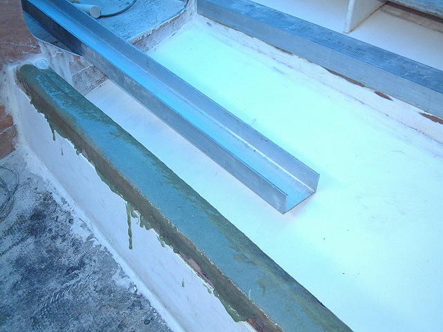
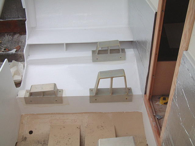
The primary aluminum caps are 6061 1/4" channel measuring 4" across on the top & 3 1/2" in the throat. The sides are 3" in outside depth.
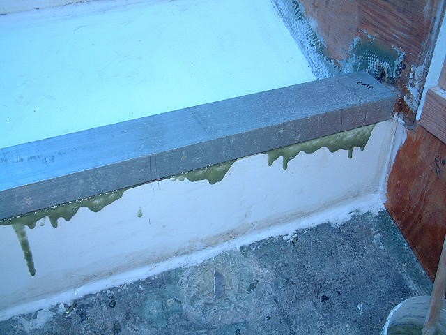
A mixture of epoxy and milled fiberglass has been added as a bedding compound for the caps. Screws or bolts are unnecessary...
Once the caps are in place, the excess epoxy is cleaned away while still wet. One of the hardest lessons that I've had to teach to those who have worked with me, is to clean all excess resins, caulks, glues, etc., from the project BEFORE it Sets Up. Left to cure, you'll be grinding, and grinding ain't your friend!
Below is final rough in and getting ready to glass the shelf to hull joint with 1208 biaxle fiberglass cloth. All work at this stage of the game is done with epoxy...
Notice also, that the new aft and forward bulkheads were in place prior to working on the engine beds...

Oh yeah, and the blue tint in the previous three images came from the blue plastic tarp that was stretched above the cockpit as a sun shade...
Skipping over all the sanding & fairing labor, here's the port engine space with a coat of Awlgrip 545 primer. The spaces will be finished with white Awlgrip top coat.
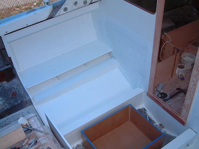
And a different angle of the starboard space...

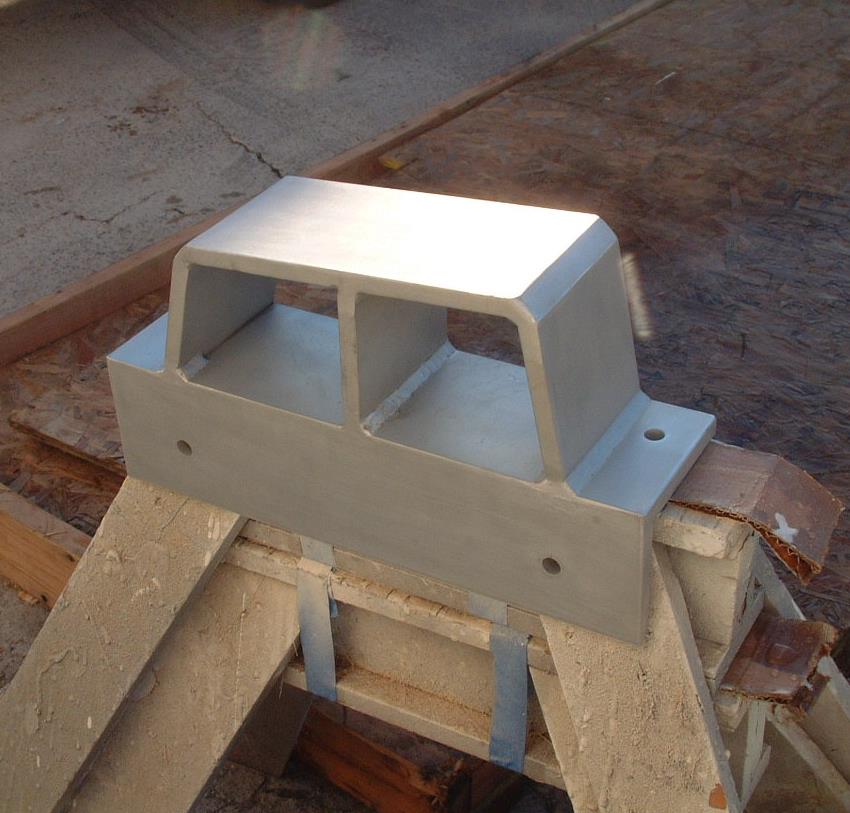
Below is the forward port engine ramp, again in 6061-T6 Aluminum. The angle and dimensions of the ramps were obtained by actually setting an engine in place, shimming it up to the correct position with scraps of wood, and then making templates for the ramp profiles. Since all bed dimensions were very close the same on both sides, only one engine was done, using the templates for both sides. The starboard ramps are a mirror image of the port.
These ramps were done in 1/2" stock, but 3/8" would have been better, plenty strong enough, and is what I'd use next time.
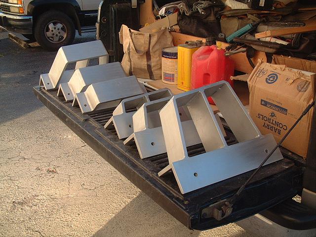
The whole set, acid washed, alodined, and ready for installation.
The next two images show the ramps setting in place after the spaces have been Awlgripped. I have waxed paper under each ramp to keep from scratching the paint. In final installation, there will be 2mm PVC Foam Board isolators under each ramp.
The outboard aft motor mount will rest on a 1/2" aluminum plate; no ramp. This was all configured to allow the engines to be at their lowest installation when complete.
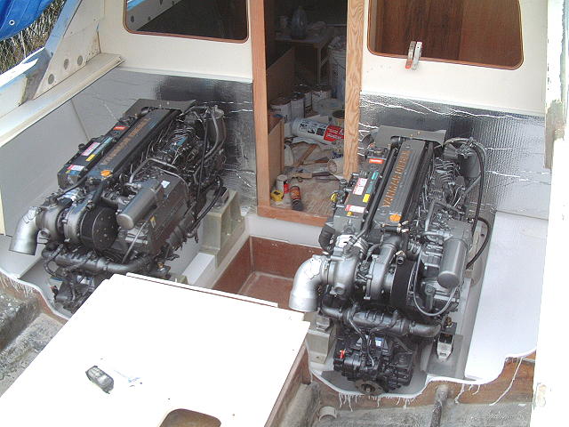
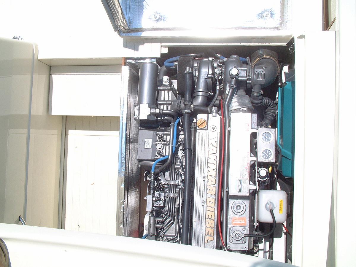
Here we are with both engines sitting in place just prior to moving "Buddy Boy" to the boat yard for final fitting before paint.
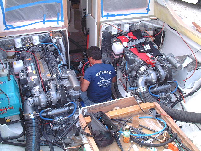
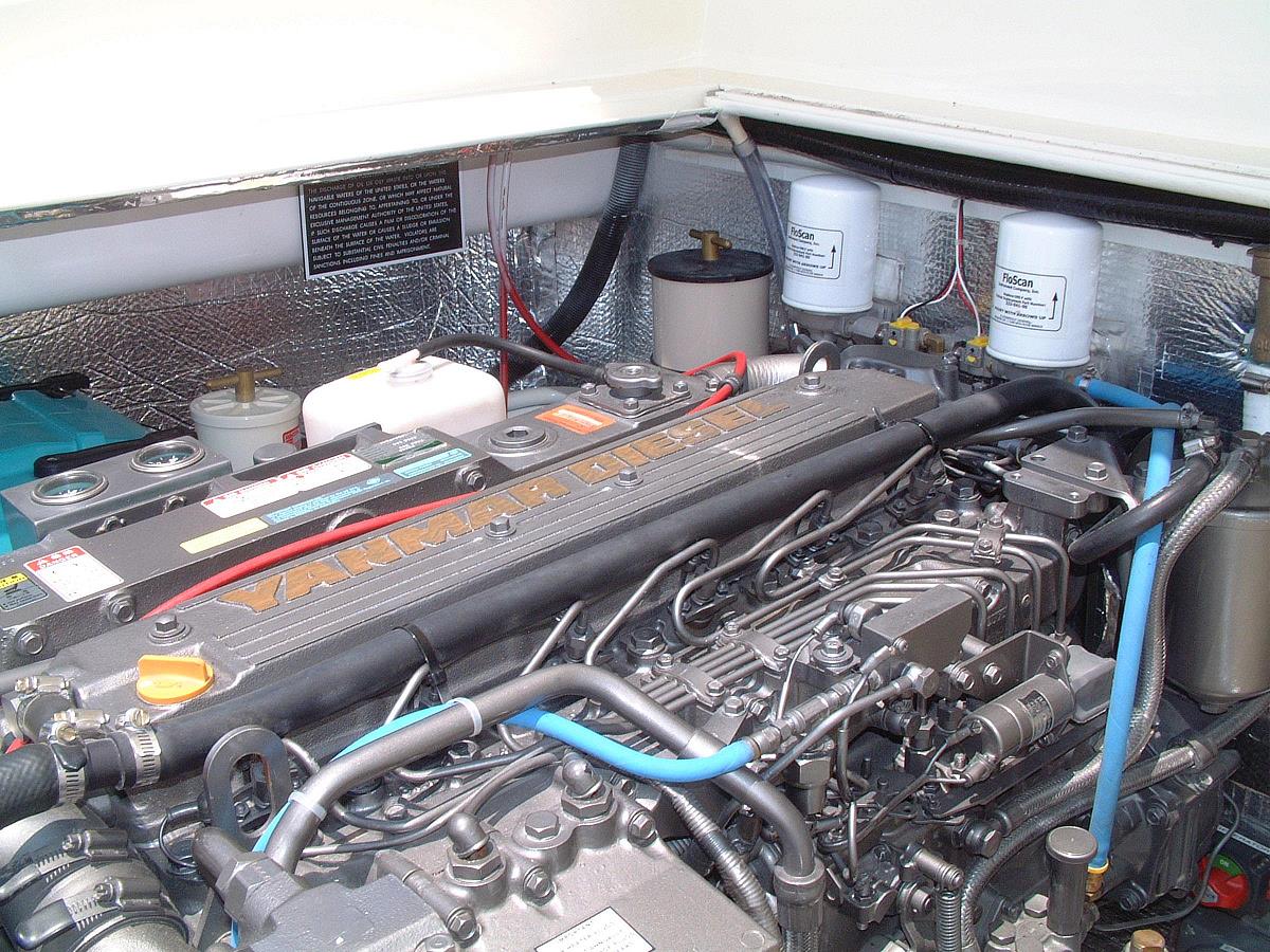
Here's Bruce doing the final installation of the engines, gen set, water heater, and all the rest of the mechanical spaces systems.
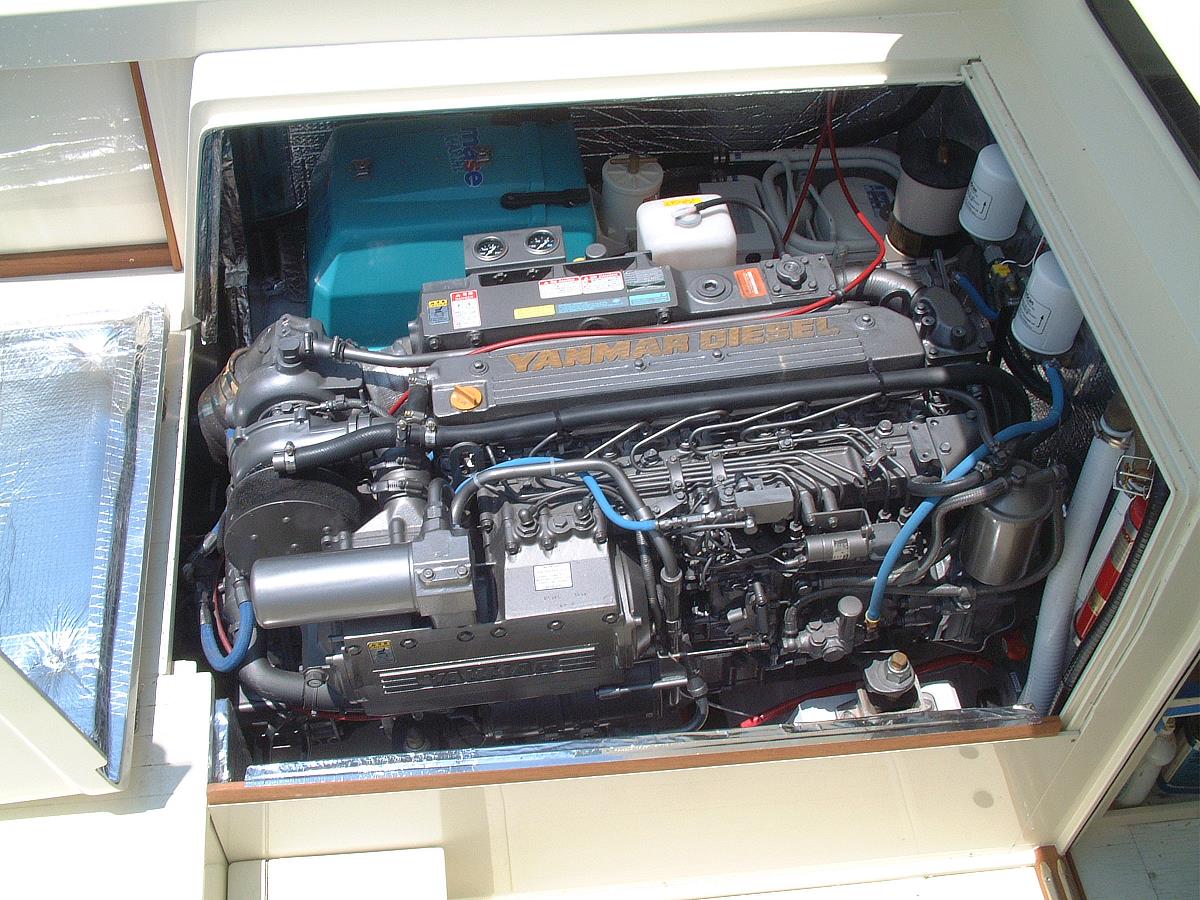
And at long last, the finished product...
 |
 |
 |
OK, so now you have a guideline to follow in designing your own repower, be it gas, diesel, or a gas to diesel conversion. Naturally, this is not the only way to design for repower, but Bruce and I feel that there is very little change that we'll make when doing this again...
Have fun! Feel free to download and print this article, but please don't use it on a website without linking it to Bertram31.com.
Capt Patrick McCrary
Bertram31.com
834 Scott Dr., LLANO, TX 78643
Telephone 325.248.0809
Web site questions or comments to: bertram31@bertram31.com