Page 1 of 1
Bonding Help- Learning the hard way...
Posted: Apr 28th, '07, 11:17
by JC
I need some help. Attached some pictures of the horror I found last time I was at the boat and opened the hatch. All bonding cables where cut out at the connections and water leaking from the rudders... Deciced to take the boat out on a lift and take all the time to fix it as I am tired of problems ive been having with my boat.... Want to redo the bonding on my boat... Where can I get instructions for this?? Props are nybral and now they are red!!.. Ive read about electrolysis so now I am sure I have a big problem. PLEASE HELP!!!
What size and type of cables for bonding system?? What materials should all hardware be??
Need urgent advice...
JC


Check out the bolts on the rudders... I am glad we did not sink!!!


Posted: Apr 28th, '07, 20:04
by CaptPatrick
JC,
Galvanic corrosion can, in the best case scenario, be an aggravation. In the worst case scenario, it can, and has, sunk boats. Galvanic corrosion may have been the underlaying cause of your shaft breaking...
Most of your questions are answered under the Building Tips section under
"Zincs, Bonding, and Galvanic Isolators".
Looks like you'll have a lot of expensive bronze hardware to be replaced. You really need to keep the boat on the hill & out of service until this problem is completely corrected. I wouldn't trust a single bolt or nut below the water line in your situation.
Use only solid. non-perforated copper strap for your primary bonding source & nothing less than marine grade 8 ga tinned wire to tap over to the individual items being protected. 6 gage is preferred...
Br,
Patrick
bonding
Posted: Apr 29th, '07, 01:22
by merlin
I've been rewiring my 31 and in addition to the stuff Capt Patrick has on the site would also recommend "The Boat Owner's Guide to Corrosion", by
Everett Collier.
There are some very good explanations of how corrosion occurs, how
current can travel from one boat to another and cause corrosion, the
benefits of an isolating transformer on the AC input etc. etc. (There is some heavy reading on chemical reactions, properties of various metals etc. but if you are not so inclined you can quickly get to the practical stuff
you want.)
Merlin
Posted: Apr 30th, '07, 22:22
by Russ
Capt. Pat, Is there any reason not to use the 8 braid copper grounding strap for a primary strip? It's only about half inch wide, but thicker than 26 guage. Or would you recomend the solid 1 inch wide strip? The braid is much more pliable and easier to work with. Getting ready to do the bonding system this week. All new plumbing and struts and hardware. Thanks in advance Russ
Posted: May 2nd, '07, 16:14
by JC
Thanks for your answers. am interested in doing this right. Can someone suggest a place to buy the bonding strap and lenght required?? I am in Central America but my partner Andre lives in Baton Rouge, Louisiana and can help out. How about hardware? All bolts should be bronze right??
How do you fix the strips to the hull??
Thanks,
JC
Posted: May 2nd, '07, 18:40
by CaptPatrick
Russ,
If you have the braided on hand, it will probably do the job... I can't say whether it's as good, better or worse since I haven't used it myself.
JC,
The 1" x 0.020" solid copper strip in a continuous length over 24" is getting kind of hard to locate. I recently purchased a 100' length from
Mead Metals Inc. in St Paul, MN. The cost on 02/26/07 was just under $1.85 per linear foot.
To do a full port and starboard run of the copper strap on a B31 you'll need between 65' & 70'. The strips are run the length of the inboard stringers, on the outboard side. The best way to attach will be with 3/4" copper nails. You'll need to pre-drill the hole for each nail...
Start by cutting your full strip into two equal pieces. Thread each piece along the stringers from the transom to the V-Berth. Starting again at the transom, secure the end of the strip that will attach to the transom zinc with tape. Lead it over to the stringer, folding as necessary to keep it flat against the surface. Place your first copper nail as far aft as possible.
You'll need the first folded tab to be about opposite the rudder port. Pull the strip tight against the first nail & your next nail will go there. Make a fold in the strip to create a tab and another nail close to the tab. The next tab will be for the struts, then the shaft alley, and so forth. The spacing on the nails should not exceed about 1'.
You might want to rig a clamp and line forward of the area that your working so that you can tension the strip along the stringer...
Use a small strip of wood & a pair of vise grips to clamp the tab for drilling with a 1/4" bit. There will be about 8 or 9 tabs per side.
Any fasteners that will go through the hull should be silicon bronze. Nuts and bolts that will tie the copper strap to a lead wire can be stainless steel, but if so, use a thin film of TefGel under the nuts and bolts.
After your done installing the strips, rub them down good with a ScotchBrite pad & put a couple of coats of paint over all but the tabs and transom zinc contact points.
Br,
Patrick
Posted: May 3rd, '07, 00:27
by merlin
Patrick,
I always assumed the stringers were wood but glassed over. Do you
have to worry about sealing up old and new holes to keep water out ?
Thanks a lot for all the details.
Merlin
Posted: May 3rd, '07, 08:07
by Skipper Dick
Capt. Patrick,
Did you purchase the soft copper or the soft annealed?
Dick
Posted: May 3rd, '07, 08:07
by CaptPatrick
Merlin,
The 3/4" marine ply in the stringers were just used as forms for the glass layup & don't significantly add to the strength of the boat. There's no need to be overly concerned about securing anything to the stringers w/o bedding.
Br,
Patrick
Posted: May 3rd, '07, 08:56
by JC
Thanks Patrick!!! That helps allot. I will probably pm if I have any specific question. I found this at consumer marine but I see its 2 inches wide.. can I just cut it out??

Copper Bonding Straps
2" x 100'L Flat Strap
Ideal for SSb installations and other grounding applications.
The previous owner had ran the bonding strap around fuel tank in those wood planks you see. Is that OK??? Or not?? I don't have a large transom zinc on my boat. Is it recomended??

JC
Posted: May 3rd, '07, 09:24
by CaptPatrick
JC,
I wouldn't bother cutting it, 2" width is going to be better than 1"...
It'd be better to install the strip directly to & along the stringers. Sooner or later that wood is going to need replacing and you'd be re-doing your bonding from scratch.
Br,
Patrick
Posted: May 3rd, '07, 12:30
by JohnCranston
Capt.Patrick,
Just one more question. How concerned do I need to be if the boat is going to sit on a trailer or my cradle lift? The bottom is going to be gel coated and the boat won't be sitting in the water. If I need to re-do the bonding, now would be the time. The glass guys are getting ready to start.
Thanks.
Posted: May 3rd, '07, 12:39
by JC
Anybody have any pictures of an installation???
Thanks,
JC
bonding
Posted: May 3rd, '07, 13:29
by Bill Cuthbertson
Is there any reason not to through bolt the strip with copper bolts to the stringers from the back side and leave the bolts standing proud for the attachment points.
Posted: May 3rd, '07, 13:44
by CaptPatrick
John,
Do it now..... Even though you're going to store out of the water, when you are in the water you'll be protected. Would you like to sit a week at Port Eads without full protection??
JC,
I started Patrick Hancock's re-bonding today. I'll post some images of the copper strip install tomorrow.
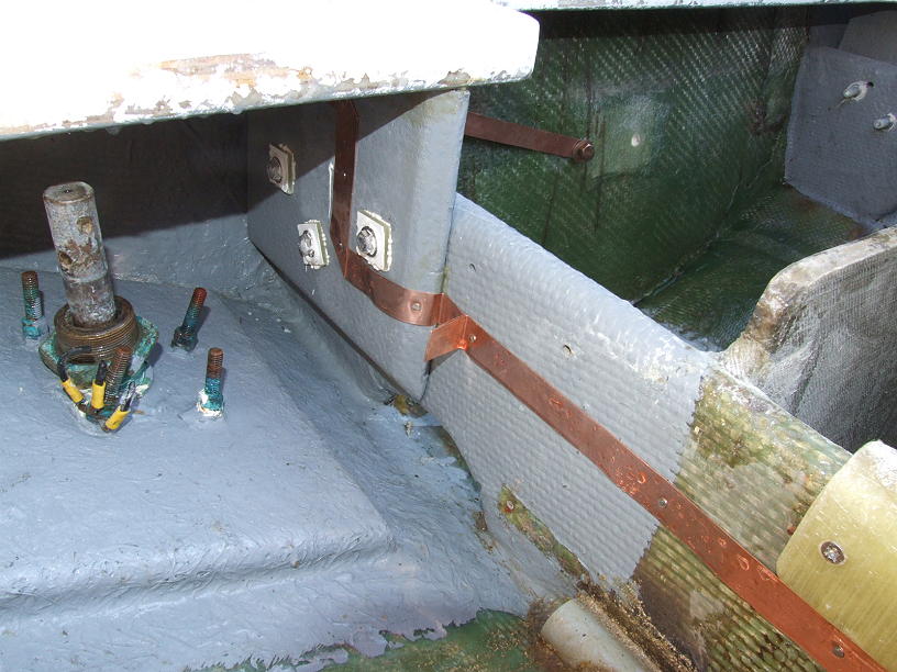
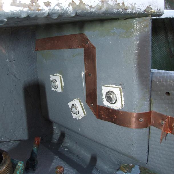
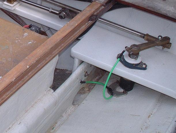
At the moment, I only have one image that I could search down. This shows the bonding from the copper strip, (glassed over & painted white), to the rudders on Jim Bailey's "Buddy Boy".
Br,
Patrick
Posted: May 3rd, '07, 21:08
by DanielM
You might want to check with consumers marine & verify the thickness of that strap. I think when I checked it was quite a bit thinner than what Capt. Pat mentions in his tips section.
DanielM.
Posted: May 3rd, '07, 21:39
by CaptPatrick
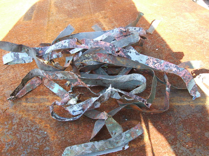
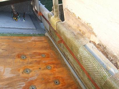
Basic installation of the copper bonding strip:
This is some of the 35 year old copper strip that was removed.
While there were some relatively OK sections, there were more
areas that were corroded beyond the point of acceptable &
more than several open gaps along the run.

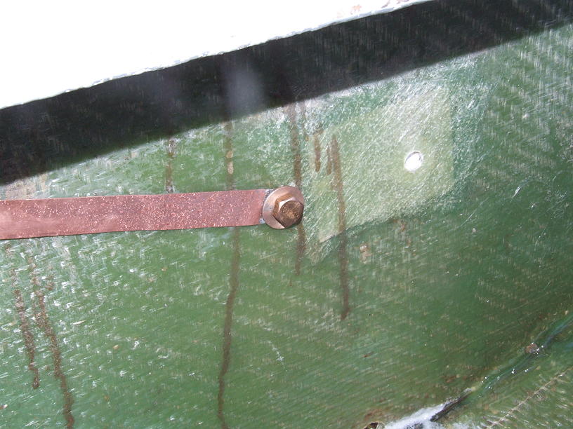
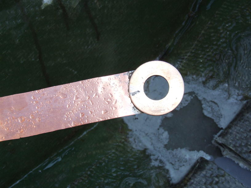
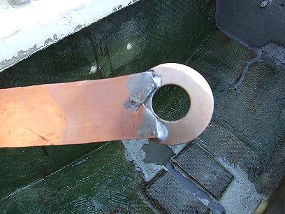
Starboard side bolt to the transom zinc. The stip was cut to proper
length & the bronze flat washer was soldered to the end.

Front view:

Back view:
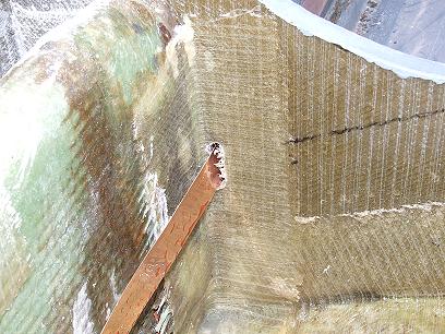
First tab; For Rudder assembly.
Angle changes are made by folding the copper over.
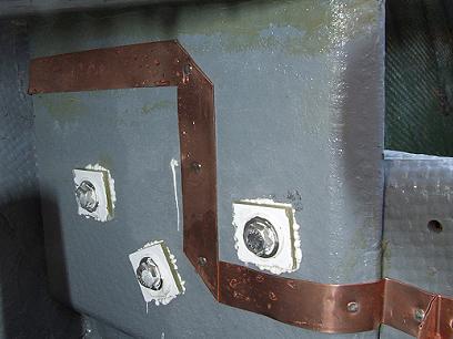
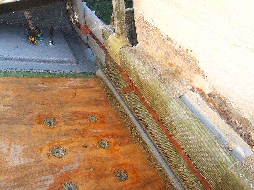
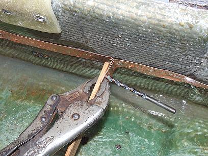
Second tab for Strut. Each tab is made by first nailing at the point of
the bend, folded loosly into the tab structure, and nailed close. The
tab is then tightly formed and ready to be drilled.
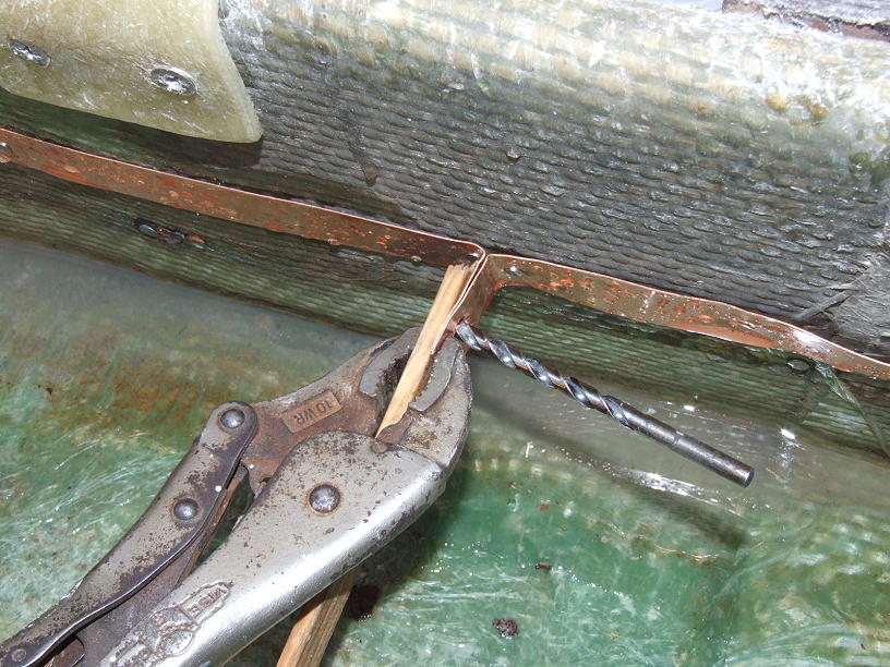
A pair of vice grips & a wooden paddle are used to clamp the tab & act
as a backing for the drill. This will keep the tab from being twisted when
the drill bit emerges.
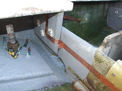
Slots are cut in bulkheads and will later be filled with resin.
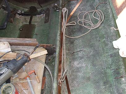
I'm using two welding clamps, one to grip the copper strip, the other
to lock onto the stringer. Using a line & stationary loop, the tension
can be pulled tight to keep the slack out of the strip.
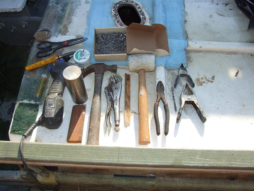
The various tools needed include soldering iron, butane micro torch,
flux, electrical grade solder, hammer, rubber malet, anvil, drill, bits,
vise grips, wood, pliers, spring clamps, and nails. I decided to use
3/4" stainless steel ring nails since I had them on hand and they can
be driven in without pre-drilling.

Once both sides of the boat get the coper strip run & the holes drilled
into the tabs, it's just a matter of connecting the item to be bonded to
the strip via marine grade wire & end connectors. Bruce and I prefer
6 ga wire, but nothing less than 8 ga should be used. Connectors should
be soldered onto the wire & glue type shrink wrap should be used over
the connectors, extending at least 1/4" beyond the connector.
(See image of rudder connection in my prevoius post.)
Where you'll have multiple attachments to a tab, keep the number
of connections to a maximum of three. If more connections will be
needed in a particular area, make more tabs.
I'll be glassing over the spaces between tabs, as was done on
"Buddy Boy", but as stated earlier, you can get by with just paint.
The point is to protect the copper from surface corrosion and to
minimumize things from catching any slack in the strip.
Like an anchor stored in the bilge...
Br,
Patrick
Posted: May 4th, '07, 10:06
by JC
WOW!!! THanks for that detailed answer. That will help a bunch. I owe you one. Maybee you want to come to El salvador and Ill take you fishing ;-) Thanks Patrick.
JC
bonding
Posted: May 5th, '07, 17:07
by thereheis
looks really nice capt pat,,,,,
phil
Posted: May 5th, '07, 17:32
by fred bortolan
Hey Capt Pat
Great pics
Im going over my bonding system now that the deck is off for tank replacment.
like alot of boats I dont have a large tramsom zincs. Is it enough just to link all thur hull fittings together or should I add one now???
Posted: May 5th, '07, 17:55
by JP Dalik
Capt. Pat,
Looks like you've got some new deck supports in the works. Like the fiberglass verticals. Is the deck rail it attaches to glass as well?
Pretty slick................
Posted: Jun 7th, '07, 13:20
by JC
Thanks for all the help. I just spent 3 days and redid bonding system... should have known its alot easier with the engines out!!!! ;-) Never knew the body could twist into so many contortionist positions!! LOL
The copper nails would all bend so had to use stainless. I just have one question now....
Ive read that there should be ONE commond ground point....
I was going to connect port bonding and stb bonding to the grounding plate found in between engines... There are 2 green wires comming from the towers which I assume one must be a grounding for the DC system and the other grounding for tower??? I was going to tie these two to the same grounding plate plus a 5th being the wire comming from the generator?? Does this sound right??
Thanks,
JC
Posted: Jun 7th, '07, 14:45
by Carl
I though the systems never got tied together, always seperate.
Motors is where I was always thrown off, its grounded thru the DC system and shaft is immersed into water. Can't see how the systems stay seperated.
I'd like to really see what the real answer is.
Hence the bump.
Posted: Jun 7th, '07, 14:48
by mike ohlstein
I don't see a choke in that Buddy Boy photo.....
Oink, Oink
Posted: Jun 7th, '07, 15:14
by JC
SIM.. I believe they have to be connected together because if not they will be 2 big pieces of connected metal and currents could flow from one side to the other. At least that is what I understood... the pourpose of connecting "bonding" the underwater items is to preven underwater current from one metal to another metal.
JC
Posted: Jun 7th, '07, 17:22
by Bruce
If you have trouble getting copper strap, I found a local roofer who will cut me copper flashing any width and is heavy duty stuff.
Used it on "Time Machine" and like Pat folder to make bends and corners.
Takes a little doing but looks real good. After while everything is clean and grease free you can coat with a clear spray to keep corrosion off.
Some copper strip has a clear coat already. Make sure you scrape at the contact points.
Posted: Jun 7th, '07, 17:49
by JC
You are right Bruce.. the roll I used was about 1.5 inches thick and it is shiny... Should I sand the areas of contact points then?? Can you comment on the commond ground point.. thanks!!!
JC
Posted: Jun 7th, '07, 19:47
by Bruce
Sanding is fine.
One strip up each side of the boat (keeps the wires short, neat and has the least amount of resistance) and if you use a transom zinc, tie the ends there.
#6 green tinned wire should be used along with tinned lugs and heat shrink tubing from thru hulls and devises to the bonding strap.
If you don't use a transom zinc, just loop it at the back.
Just a note about tying in the engine blocks to the bonding system:
Make sure the engines are connected together, block to block with a battery ground cable.
Don't use the bonding system to make a common ground connection.
Posted: Jun 8th, '07, 13:04
by Carl
Okay tying the shafts and props thru the motors to the bonding system makes perfect sence to me with one exception which is where I always seem to get balled up...if you tie the bonding system to the motor, shaft n prop then you are also tying in the DC system as well...aren't you. The DC system has its main leg going right to the block.
Posted: Jun 8th, '07, 17:29
by CaptPatrick
Carl,
While bonding and grounding are two different topics, they do share the same DC ground.
Bonding ties all necessary metals needing protection from galvanic corrosion to various sacrificial zincs, which is grounded through contact with the water.
DC Grounding is part of the electrical path to the battery. The engines have both DC grounding & bonding connections. The shafts are not necessarily well bonded just because they are connected to the engines. For a good bonding of the shafts, I use shaft brushes that make direct contact between the shaft and the bonding system.
So, in other words, you wouldn't ground your radio to the bonding system or bond your through hull fitting through the negative battery cable, but both systems are grounded to earth via the engine blocks.
Br,
Patrick
Posted: Jun 8th, '07, 18:00
by Carl
Capt Pat,
I honestly think I can say I really understand now. Tomorow...well that is another story, I think I'll print out that explaination and re-read every now and then.
Thanks for explaination.
Carl