Page 1 of 1
DC Wiring during Repower
Posted: Jan 23rd, '14, 12:19
by JohnV8r
With my gas engines I have two dedicated circuit breakers on my DC panel for the ignition on each engine. Will I need similar dedicated DC circuits for the Cummins 6BTA's since there is no ignition per se on a diesel engine?
Re: DC Wiring during Repower
Posted: Jan 23rd, '14, 12:46
by longfin
Short answer is yes you should have a breaker for each engine. You will have start stop switches or buttons, or even a key switch at the helm and the panel breakers provide power for that circuit.
Re: DC Wiring during Repower
Posted: Jan 23rd, '14, 13:37
by JohnV8r
Thank you!
Re: DC Wiring during Repower
Posted: Jan 23rd, '14, 16:15
by Bruce
John,
You have to be careful with the panel wiring if your using 3 separate circuits, house, port eng and stb eng.
If you run a circuit off each engine up to the panel don't take the feed off the panel itself otherwise you will combine the three circuits and will cause issues.
Run the ignition/on for each engine in a loop up to the panel to individual breakers for port and stb. not tied into anything else or any buss bars.
I also run a kill circuit switch in the loop back to the engine and hide the switches as an anti theft.
While a decent mechanic can jump everything right from the engine, most will quit and walk away.
There are plenty of spaces to hide them yet still easy to get to.
Re: DC Wiring during Repower
Posted: Jan 23rd, '14, 17:45
by JohnV8r
Bruce,
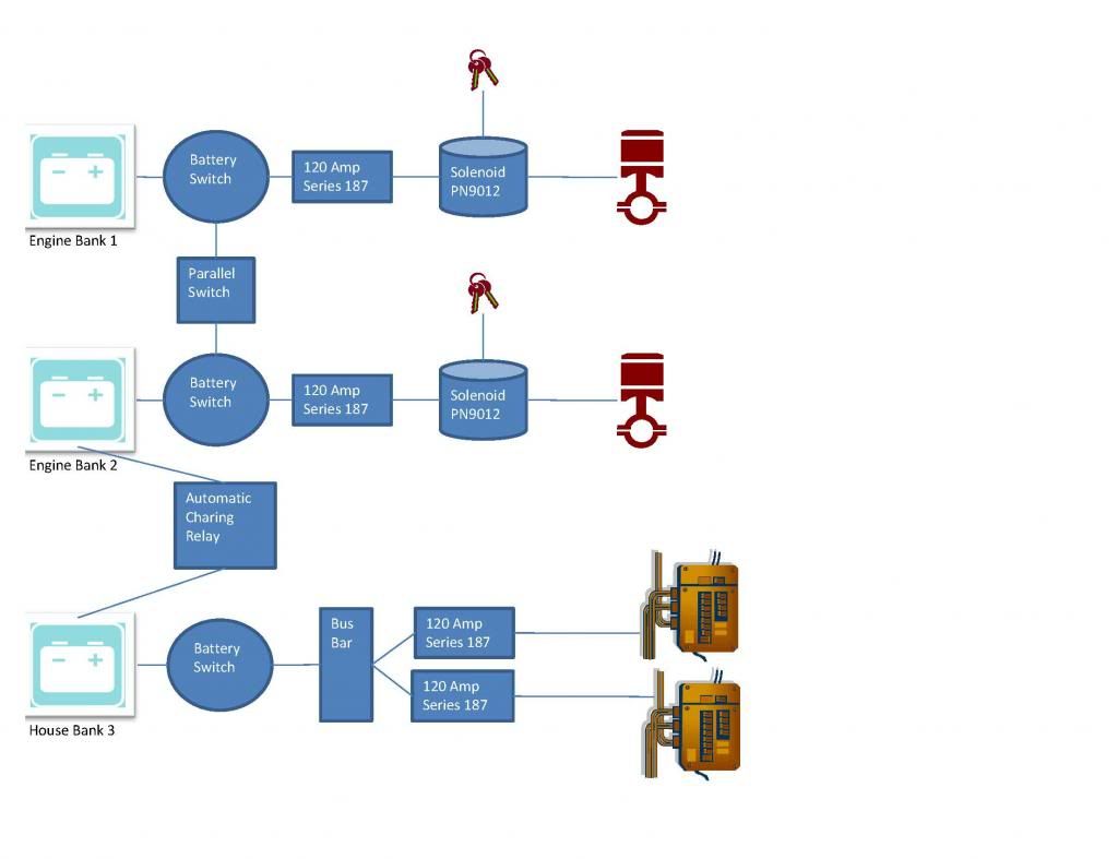
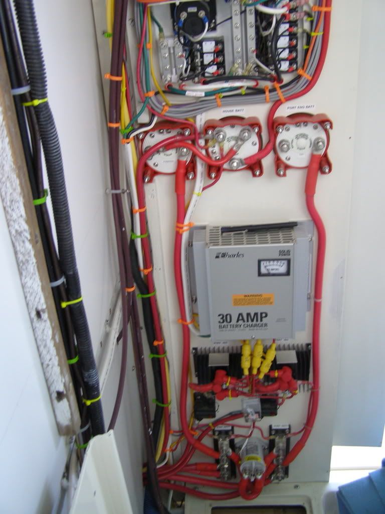
Below is the preliminary layout that I penciled out for the DC side when I was sourcing and pricing parts. Would there be an issue under this schematic? I will run an invertor - I have no need for a generator. My biggest concern with the schematic below was whether I should be running the automatic charging relay (ACR) from the House Bank 3 to Engine Bank 2 or vice versa. The house bank will be larger than Engine Bank 2. I read during my research you should put the larger battery bank in line to be charged first, which left me concerned that if I put the larger house bank in line first the engine bank might not get fully charged.
I already had Lewco update/upgrade my battery charger to a three bank with a selectable charge rate for Wet, AGM, and Gel batteries so I am sure leaving the dock all three banks would be charged.
With the gas engines, I was just running two battery banks and had rewired the panel so that all the DC items that might have been run while I was at anchor were on the starboard bank. That way, if I ran the starboard battery bank down overnight, I could flip the parallel switch to start the starboard engine. I gotta be honest, I have never looked to see where my alternators connect into my two bank system and have always assumed they went straight into the battery banks. How should I be connecting the alternators into the DC system with the repower?
Re: DC Wiring during Repower
Posted: Jan 23rd, '14, 18:17
by JohnV8r
Bruce,
Sorry, I just reread your post. I'm working on about four hours of sleep today, so I'm a little slower on the uptake than usual. I understand what you're saying about creating independent loops. Will do.
Thanks,
John
Re: DC Wiring during Repower
Posted: Jan 23rd, '14, 22:20
by Joseph Fikentscher
John,
I'm not sure I understand Bruce's post. But I need to rewire my 25 in the same basic way as you are doing. One battery for each motor and one house battery. I have a 3 bank charger that seems to work well, keeps the batteries topped off. When you finalize your plan, could you send a copy to me? I am basically electrical illiterate.
Thanks,
Joe.
Re: DC Wiring during Repower
Posted: Jan 24th, '14, 00:00
by JohnV8r
Joe,
If you look at the back of a "modern" marine DC circuit panel, you will see that there are "bus bars" that connect to all the positive feeds of the individual circuit breakers. You simply connect the positive lead from the battery to bus bar (after you've gone through the ABYC required battery switch and fuse) and all of your circuit breakers on that bus bar are now hot. You can see a diagram from BlueSea's installation instructions for a standard panel with a bus bar on page 2 here:
http://assets.bluesea.com/files/resourc ... s/9863.pdf
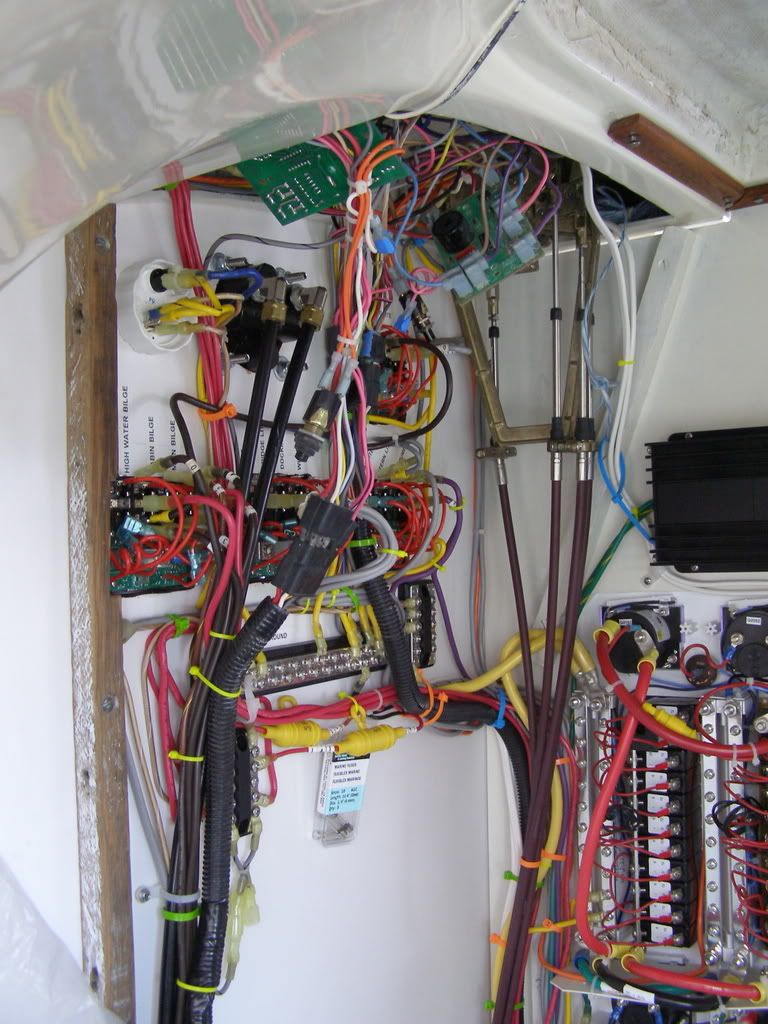
My B31 (Shambala) has the old "house" style DC circuit breaker panel, which looks like this (with the front taken off):
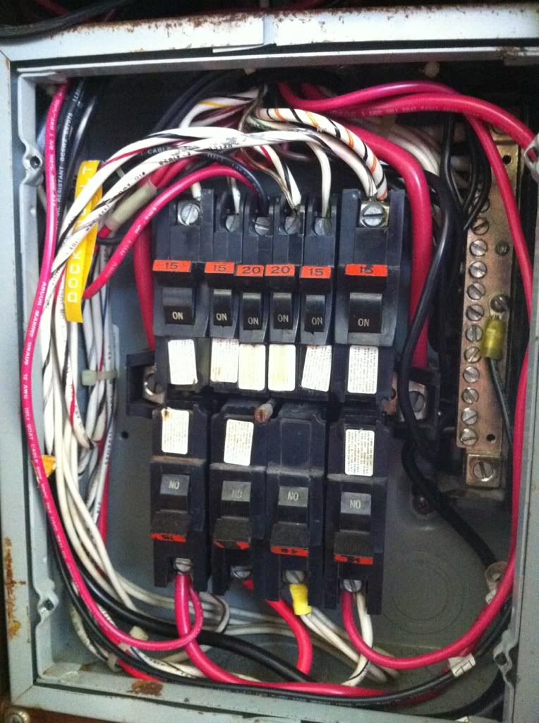
On the house style DC panel, the port engine and starboard engine circuit breakers were independently wired directly to the separate batteries and not connected to the same bus bar as the other DC accessories. I believe the reason for the separate wiring had to do with the potential for a significant voltage drop when you fired the engines from the keyed or push button ignition. It's the old water pipe analogy about DC current and how much current it takes in the initial engine cranking. There's not enough current in the pipe so to speak for all the DC items AND the starter if you're wired through the panel/bus bars. You still get the same issue with sensitive electronics like a radar or chartplotter when they are connected to the same battery bank as the starter for the engine. Sensitive electronics will end up restarting themselves when you fire the ignition because of the voltage drop in the battery bank when the ignition/starter is fired.
What I interpreted Bruce to be saying is that the starter/ignition circuits need to continue to be independent from other DC bus bars and direct wired accessories so you don't create a voltage drop that impacts their ability to function while starting. The kill switches he is talking about are a simple hidden break in the circuit to keep someone from getting on board and starting the engines by just turning on the circuit breakers in the panel.
The way you accomplish putting an independent circuit in a panel in the diagram on the link I provided above is to simply remove the bus bar and cut the length down so two of the circuit breakers are not being contacted by the bus bar. You then wire your positive and negative feeds directly from the battery to the circuit breaker (using the required ABYC fuse and connection standards along the route) and to the ignition key or toggle/push button. The negative side will have to return to the negative post of the battery independent of any other negative bus bars that tie the negative side of other DC circuits or accessories to the post.
I hope I understood Bruce correctly and that this makes sense to you. It's about the best I can do on no sleep at this point. If it doesn't, let me know what parts are unclear and I'll try to clarify. I'm sure Bruce or someone else will chime in if I misinterpreted Bruce's post. However, I'm pretty sure I got it right.
By the way, the automatic charger relay (ACR) in my diagram is designed to allow the 3rd bank to charge from the same alternator that recharges Engine Bank 2 while you are the engines. Additionally, it isolates the 3rd bank from the starting bank when it senses the huge voltage drop that occurs during engine cranking. This prevents your sensitive electronics from recharging. It is important to install the ACR
before the battery switches to have it work correctly.
Hopefully Bruce will jump in here if this is not correct/clear. Bruce has undoubtedly forgotten more about DC circuits than I have ever known. He's a much more comprehensive resource than I am.
Good luck.
John
Re: DC Wiring during Repower
Posted: Jan 24th, '14, 07:55
by Bruce
John,
You have it correct.
I've seen numerous times where a ignition loop was run to the dc panel and connected to the panel and tied in.
Without isolating the port and stb circuits, the house, port and stb are all connected creating numerous situations where if one is anchored on house power it will draw down all batteries or the more dangerous is if one engine battery is dead it could pull high current back thru that ignition loop from the other engine or house system to try and start. This could lead to wire overheat and fire if not wired correct on the breaker load vs feed side or there isn't a load breaker at the engine. Not all engines have that ignition load breaker.
Not so much a problem for voltage drop as the ignition circuit is relatively a light load unless some genius tied the alt back into it, the load of course is the start cable from the battery.
Whats the reason for the solenoids and 120amp to engine? Also on the parallel remember if you feed the coil from a battery and that battery is the one that goes dead the parallel will not work.
I'm an old switch guy myself. Electronic connections are nice but I've thrown to many away.
I like the idea if one has a dead battery rather than hit a parallel on the bridge, you have to open the engine compartments to turn a switch and that makes one look at possible issues or trouble.
Re: DC Wiring during Repower
Posted: Jan 24th, '14, 10:37
by Joseph Fikentscher
Thanks, John and Bruce. As you can see the wiring on my 25 is all over the place. Nothing is marked, wires everywhere, i don't even know where to begin. But it must be done. Gauges don't work, everything looks corroded, wires cut, wires jumped, just a mess.


The starting batteries (one for each motor) do have switches (1, 2, both, off) but no fuses. There is what seems to be an isolator (Guest) but the MFGR didn't even know what it was. Must be old. There is a Promite 5-5-3 charger that seems to work well. A house battery (in the picture) runs some stuff but I don't know what. Bilge pumps run directly off the starboard starting battery.
Not knowing what is what makes it difficult, especially for a non-electrical brain such as mine. Any thoughts or assistance is greatly appreciated.
Regards,
Joe
Re: DC Wiring during Repower
Posted: Jan 24th, '14, 12:16
by Bruce
Joe,
Unless you rip out everything and start over(sometimes easier) your going to want to get to know a multi meter.
The ohm or continuity portion is a must when finding what one end of a wire belongs to what other end to indentify circuits.
If you not sure or familiar with using the ohm portion of a multi meter to trace circuits I can post a tutorial if you'd like.
Re: DC Wiring during Repower
Posted: Jan 24th, '14, 12:56
by JohnV8r
Joe,
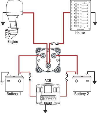
Where to start is fairly straight forward. You will run a cable from your positive side of your battery to your battery selector switch. Coming out of the battery selector switch is where you will put a fuse/high amp breaker. Instead of the old monster sized automotive looking fuse, you will want to put in one of these surface mount Series 187 breakers (probably in the 120 amp range):
http://www.bluesea.com/products/categor ... 187-Series
This breaker basically protects your system from something catastrophic that would likely melt all your DC wires and catch your boat on fire. From the 187 Series breaker, you will run a hot/positive wire in the same size to the new DC panel you select. You have all kinds of options for panels:
http://www.bluesea.com/products/category/DC_Panels
You run hot/positive wires from you DC panel to all the DC accessories you want to power.
The ground or negative side of the DC circuit is even more simple. You come off the negative post on the battery, install a bus bar where convenient, run a large wire to convenient area (most commonly where your panel is), and install another bus bar to tie in all the negative/ground sides of the individual circuit breakers on your panel. That sounds more complicated than it is. Trust me; it's straightforward.
Here's a simple overview of what I just described. Ignore the 2nd battery in this diagram for a second and just follow the wiring from the battery to the panel. The squiggly line is the Series 187 breaker.
As for figuring out the morass of wires in your B25 currently, you have two options: 1) Just ignore it all and pull it out since you're going to rewire everything anyway, or 2) follow the wires to figure out what they go to and replace them one at a time. However, keep in mind you're not going to simply redo everything the same way it has been done/modified over the years. The reason why you can just ignore it is because for the most part you will know what accessories need to have power and you're just going to wire them to the panel on a rewiring project.
I would recommend one additional (from the ignition circuits) deviation from running everything through the bus bar on the panel. That would be for your bilge pumps. I have four bilge pumps on Shambala, with one a full time "on" bilge pump with a float switch that is connected directly to the battery bank with the least DC load on it. It is a fail safe in the event something happens - like the time my diver disconnected my shore power and forgot to plug it back in. I recommend at least one of your bilge pumps come straight off the batteries. Run a #8AWG size wire from a battery directly into a Series 187 breaker. The Series 187 breaker gives you the ability to switch the full time "on" bilge pump off in the event you want to turn it off for the winter or replace it, etc. I would run the same #8AWG positive wire up to a terminal block like this:
http://www.bluesea.com/products/2502/Te ... _2_Circuit
Wire in the bilge pump and float switch to this terminal block per the bilge pump manufacturer's instructions. Be sure to include an inline fuse per the manufacturer's instructions as the new mercury free float switches are prone to failure and can actually melt/start a fire if they get hot (they are terrible, but are a necessary evil). You can use the other side of the terminal block to connect the negative side that you will run to the negative post on the battery. One last note on wiring directly to the battery: ABYC standards require a terminal block between the battery and the accessory. Don't skip the terminal block or you'll get a recommendation to correct it during a survey.
Good luck. Fire away with any questions, and someone here will get it answered. Boat wiring is not as daunting as it seems. I didn't know that much about wiring until I was forced to deal with it. There are some nuances, but you can learn those here by asking questions along the way.
John
Re: DC Wiring during Repower
Posted: Jan 24th, '14, 13:12
by Joseph Fikentscher
Bruce,
Thanks, a tutorial would be helpful. I have a couple of multi-meters but only have used them to test the batteries.
John,
Thanks. Seems so simple the way you say it. I will be drawing some diagrams to help me visualize what I need to do. As for actual work it's going to need to get warmer!
Re: DC Wiring during Repower
Posted: Jan 24th, '14, 13:44
by CaptPatrick
it's going to need to get warmer!
I feel your pain Joe... It's 12 degrees warmer in Anchorage than it is down here on my front deck.
Re: DC Wiring during Repower
Posted: Jan 24th, '14, 13:53
by JohnV8r
Joe,
The good news is the heavy mental lifting - planning and diagraming what you're going to do - is done before you do a single thing to your boat. Any mistakes you might be making can be prevented by posting your plan here and having others look at it. It's like a wide receiver running a route at football practice; if the QB and WR both know where the WR is going, it's relatively simple to get him the ball. If you wing it, anything can happen.
Pulling wires and getting into spaces that Justin Bieber's monkey would struggle to get into is where rewiring a boat can make you want to jam a pen in your neck...but you can get through in one piece.
Good luck,
John
Re: DC Wiring during Repower
Posted: Jan 24th, '14, 20:33
by Bruce
I'll post something up sometime Sat. on the meter.
Re: DC Wiring during Repower
Posted: Jan 24th, '14, 23:09
by Tony Meola
John
I am looking to replace my breaker box also. Trying to decide which panel to use, that will fit in that spot. Did you find one that fits without to much alteration needed?
Re: DC Wiring during Repower
Posted: Jan 25th, '14, 01:59
by JohnV8r
Tony,
Your very best DC panel option are the new Blues Sea 360 panels. A two wide panel will fit in the location of the original house style box. I am going to put a 5x2 panel in Shambala. I think it was the 4x2 panel actually would fit in the in the house location. It's the width of the 360 Panels that fit in that forward bulkhead cabinet. Nothing else fits perfectly. Also, you get to customize the panel to have whatever you want which is awesome. Use the panel wizard here:
http://panelwizard.bluesea.com/
If you register with Blue Sea, they save your configuration so you can edit it and play around with different configurations. Once you've decided, you get to select the circuit breaker size (amps) and the labels for each location. When you order, you will tell Blue Sea where you want your quote sent to. Ask them to recommend an out of state internet based distributor where you can get the panel for less than the list price and avoid paying sales tax.
You'll like these panels. I think they're the best available and, frankly, the only option to fit in the cabinet space where the original house box was.
Good luck,
John
Re: DC Wiring during Repower
Posted: Jan 25th, '14, 02:13
by JohnV8r
One other thing about Blue Sea: Their tech support guys are great. I have called them on several occasions to ask about certain products applicability for my planned installation. I'll give you an example of one of the more nuanced things they helped me with: I knew I needed an automatic charging relay to have a 3rd battery bank. However, I was thinking I would put it just past the battery selector switches because it would facilitate a more convenient mounting location. The tech support guys at Blue Sea told me the ACR would work in that location to charge the 3rd bank. However, they recommended I put the ACR in front of the battery selector switches (between the batteries and the switches) because the there are a couple of extra nano seconds involved when the current to the ACR sensing has to go through a battery selector switch. When the voltage gets slammed during engine cranking, it makes a difference to any sensitive electronics like my Furuno Navnet on the 3rd bank because the Navnet unit is designed to sense a sudden voltage drop and shut itself down to protect itself.
The fact that they love talking about installation issues BEFORE I have even installed the product is phenomenal. It's not like you have to call in and give them your product registration information.
Re: DC Wiring during Repower
Posted: Jan 25th, '14, 19:16
by Tony Meola
John
Thanks. I will take a look at the 360 Panels. For some reason I did not think they would work. I used their diesel battery switches for the engines. I really like them. Nice and smooth. Make the Perko and Guest feel like %^$#. They are smaller too giving you more places that you can stick them in.
Tony
Re: DC Wiring during Repower
Posted: Jan 27th, '14, 16:34
by Bruce
Joe,
Didn't forget.
Between trying to get FPL(power company) to replace the drop between the house and pole(cheap ********) and my sister dumped elderly parent financial mess in my lap, give me a day or so to knock heads and I'll get something up.
Re: DC Wiring during Repower
Posted: Jan 28th, '14, 07:50
by Joseph Fikentscher
Thanks, Bruce.
I know, the family stuff can get tough. I've got Mom in assisted living and a sister that eagerly asks for money at every turn.
Take your time, I'm not venturing out till it warms up a bit.
Regards,
Joe
Re: DC Wiring during Repower
Posted: Jan 31st, '14, 22:16
by CaptPatrick
Re: DC Wiring during Repower
Posted: Jan 31st, '14, 23:18
by Tony Meola
Now that is a classic. LMAO
Re: DC Wiring during Repower
Posted: Feb 1st, '14, 10:08
by JohnV8r
LMAO!!! My son asked where he could sign the "Deport Justin Bieber" petition last week. I almost choked to death on my coffee I was laughing so hard!
Re: DC Wiring during Repower
Posted: Feb 1st, '14, 11:10
by CaptPatrick
JohnV8r wrote:My son asked where he could sign the "Deport Justin Bieber" petition last week.
Deport Justin Bieber and revoke his green card
Re: DC Wiring during Repower
Posted: Feb 1st, '14, 14:33
by Mikey
Joseph,
Start over. Much easier in the long run. There is no way to know the condition of the wire you have nor where the hell its going, even with a meter and plenty of time on your hands. I cut two #10 Wheelings full of wire from Dreamsicle and recycled it for the copper. Took me six weeks to map out and plan my schematic. Had
lots of help from the sandbox. There is no such thing as a dumb question. With a pair of Cummins, three Opti batteries and the desire for simplicity (Yea, that'll happen) I got this. Very glad now that I took the time and the $$$.
Need new pix, there is a lot more to this "Simple" system now.


