I was wondering if installing a small fuel pump into the fuel system would be a bad idea.
I figure it could be used to prime the system and be installed near the fuel tank. When I fired my engines up after the rebuild I used this pump to feed the system from a bucket of diesel fuel and it worked great.
I think my manual lift pumps on the side of the engine dont really work that well and have been scratching my head about using the electric pump.
I was thinking about if it was needed I would have it plumbed into both fuel lines that go to port and starboard engines, this would be so I would only need one pump.
I am thinking of having a "tee" off of each pickup tube from the tank then to a shut-off valve for each side. the two feeds from each "tee" would then go to another "tee" to basically "Y" into the pump.
The output of the pump would "tee" off thru another set of shut-offs and back to the main lines respectively.
I know it sounds confusing but I am figuring that the electric pump should be isolated from the fuel supply when it is not in use and if needed you just need to open two closed shutoff valves and then activate the switch to turn it on.
Is this feasible or impracticle?
Frank
small 12v diesel pump for priming?
Moderators: CaptPatrick, mike ohlstein, Bruce
-
scenarioL113

- Senior Member
- Posts: 689
- Joined: May 31st, '08, 09:00
- Location: Massapequa Park, NY
small 12v diesel pump for priming?
1971 28 Bertram
4BT Cummins
Frank
9-11-01 NEVER FORGET
4BT Cummins
Frank
9-11-01 NEVER FORGET
-
scenarioL113
- Senior Member
- Posts: 689
- Joined: May 31st, '08, 09:00
- Location: Massapequa Park, NY
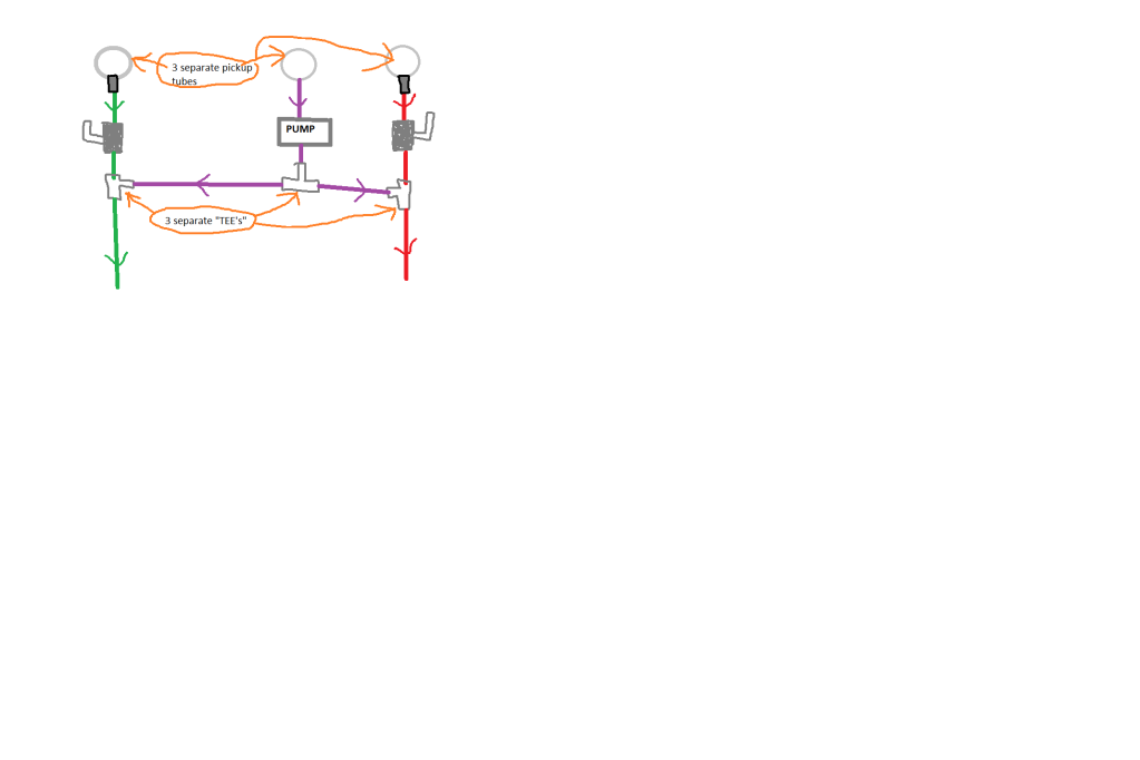
This is a cheesey diagram I drew with paint but it visualizes what I am talking about.
The gray things are the "tee"'s red is starboard fuel line and blue is port. Green are the shutoff's. The purple line id the line that would be getting primed when the shutoffs are opened.
They would normally remain closed at all times unless needed. This entire idea would be manually used.

The gray things are the "tee"'s red is starboard fuel line and blue is port. Green are the shutoff's. The purple line id the line that would be getting primed when the shutoffs are opened.
They would normally remain closed at all times unless needed. This entire idea would be manually used.
1971 28 Bertram
4BT Cummins
Frank
9-11-01 NEVER FORGET
4BT Cummins
Frank
9-11-01 NEVER FORGET

They way you have it designed it could potentialy just recirculate in a loop.
What you want is to add a fuel shut off in the main line between the inlet and outlet of the pump and shut it when the pump is on.
Use a low pressure pump and if all this is before the fuel filters, the pump can clog from debris. Some pumps have a screen filter for small micron particles but no real surface area for larger debris.
Pumps are good ideas.
-
scenarioL113
- Senior Member
- Posts: 689
- Joined: May 31st, '08, 09:00
- Location: Massapequa Park, NY

-
In Memory Walter K

- Senior Member
- Posts: 2912
- Joined: Jun 30th, '06, 21:25
- Location: East Hampton LI, NY
- Contact:
-
scenarioL113
- Senior Member
- Posts: 689
- Joined: May 31st, '08, 09:00
- Location: Massapequa Park, NY
-
scenarioL113
- Senior Member
- Posts: 689
- Joined: May 31st, '08, 09:00
- Location: Massapequa Park, NY
Will fuel flow without a problem through the pump when the pump is not in use?
I am using this pump:
http://performanceparts.com/part.php?partID=414573
I am using this pump:
http://performanceparts.com/part.php?partID=414573
1971 28 Bertram
4BT Cummins
Frank
9-11-01 NEVER FORGET
4BT Cummins
Frank
9-11-01 NEVER FORGET
-
scenarioL113
- Senior Member
- Posts: 689
- Joined: May 31st, '08, 09:00
- Location: Massapequa Park, NY
If I do install a primer pump I will use it. I did see the recommendation on there website and I dont see any reason why it would be a problem.
I am sure the recommendation is because they will not warranty it in the marine environment, since many people will not solder and heat shrink connections etc....etc.....etc....
If we were talking about a gasoline application then I would be more hesitant.
So what about inline, will these type of pumps allow product to free flow thru when not operating allowing it to be connected inline???
1971 28 Bertram
4BT Cummins
Frank
9-11-01 NEVER FORGET
4BT Cummins
Frank
9-11-01 NEVER FORGET
Yes many of that design will, but you should contact the manufacturer to be sure and also ask what the free flow rate is and what your engines need for GPH flow. There was no technical info on the manufacturers web site.
If you have Cummins engines, I would not recomend that pump as an inline pump.
If your going to use two pumps anyway and get away from the free flow issue, it would only take 1 valve.
On your main fuel feed line create a loop off it with two t's for the pump.
Then in the main line between the loop ends put the shut off valve.
Close when using the pump so it doesn't just recirculate.

-
Tony Meola
- Senior Member
- Posts: 6948
- Joined: Jun 29th, '06, 21:24
- Location: Hillsdale, New Jersey
- Contact:
-
CaptPatrick

- Founder/Admin
- Posts: 4161
- Joined: Jun 7th, '06, 14:25
- Location: 834 Scott Dr., LLANO, TX 78643 - 325.248.0809 bertram31@bertram31.com
About $400 a pop for the 12v model... And only for the 900 & 1000 Racors.Not sure how expensive it
http://www.foreandaftmarine.com/62-RKP1912.htm
-
scenarioL113
- Senior Member
- Posts: 689
- Joined: May 31st, '08, 09:00
- Location: Massapequa Park, NY
How about this:
The two fittings off the main pickup tubes (the outside ones) have fittings that have check valves in them before the shutoffs. I could probably run it like this and not have to ever turn any valves.
I can shut the valves if I had to though. I dont see any snags and fuel for the pump comes from its own separate pickup tube assembly and fuel will not travel thru the pump unless the pump is running. I dont have to worry about the pump getting clogged and messing up my fuel system.
What do we think about this setup???
1971 28 Bertram
4BT Cummins
Frank
9-11-01 NEVER FORGET
4BT Cummins
Frank
9-11-01 NEVER FORGET
Check valves?
Unless your carbureted gas, those things don't belong.
You will put undue suction on the engine primary pumps and cause premature failure. Also you can aerate the fuel and cause bubbles with check valves due to the increased suction.
Your last pic will work but I'd add a shut off in the crossover when running normal.
-
scenarioL113
- Senior Member
- Posts: 689
- Joined: May 31st, '08, 09:00
- Location: Massapequa Park, NY
-
scenarioL113
- Senior Member
- Posts: 689
- Joined: May 31st, '08, 09:00
- Location: Massapequa Park, NY
-
scenarioL113
- Senior Member
- Posts: 689
- Joined: May 31st, '08, 09:00
- Location: Massapequa Park, NY
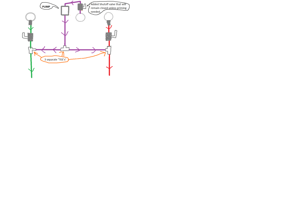
I amended my plan and it is shown in the previous post. This should work without all the redundant shutoffs like I was thinking early on. With the shutoff at the pumps pickup tube it will not allow the engines to draw fuel through the pump when not in use.
When the priming pump is used the valve will get opened and both systems will get primed, which is OK.
If for some reason a need arises that I can only have one side (port or starboard) being primed then I can shut either side down respectively at the racor filters. I have already installed shutoff valves on the input and output sides of them.
Since this system is only to be used manually I guess it would be stupid to install the on/off switch at the bridge. I will either install the switch at the filters (in engine compartment) or at the pump which is at rear of the tank near rudder arm.
I hope this thread has been informative to those who may to do something similar.
Frank
1971 28 Bertram
4BT Cummins
Frank
9-11-01 NEVER FORGET
4BT Cummins
Frank
9-11-01 NEVER FORGET
Who is online
Users browsing this forum: Google [Bot] and 223 guests