Hey Guys,
Primed the fuel system on Shambala tonight and tried to start the motors to make sure they would fire when I splash on Monday. Gas is squirting from the jets in the carburetors, but I don’t seem to be getting any spark on either engine. No fire at all. Checked the voltage on the tops of the coils and got 4.52 volts port and 4.33 volts starboard. Is that normal voltage on the coils?
Couldn’t try to check for a spark properly because I was by myself and really didn’t want to try to start the motor with a screw driver while checking for a spark.
Looking for feedback on the coil voltage and what to check next if that is normal voltage.
Thanks in advance.
Coil Voltage
Moderators: CaptPatrick, mike ohlstein, Bruce
-
JohnV8r

- Senior Member
- Posts: 625
- Joined: Jun 29th, '06, 21:59
- Location: Northern California Bay Area
- Contact:
Coil Voltage
Bertram 31 - The Best Boat Ever Built
Re: Coil Voltage
Coil voltage would depend on what type of ignition system you have and whether you have an external ballast resistor. My starboard engine has a Mallory distributor with an electronic conversion insert kit. Voltage at the coil is 12. My port engine has a Prestolite system, also electronic. Voltage at that coil is 6 but goes up to 10 with the engine running.
For testing, I connected a starter button to two wires with alligator clips which I can connect to the two terminals on the starter solenoid. Harbor Freight sells an simple inline spark checker consisting of a short length of spark plug wire and a light bulb. You pull the wire off of one plug, plug the tester onto the plug, and attach the existing plug wire to the other end. If the light flashes, you have a spark.
For testing, I connected a starter button to two wires with alligator clips which I can connect to the two terminals on the starter solenoid. Harbor Freight sells an simple inline spark checker consisting of a short length of spark plug wire and a light bulb. You pull the wire off of one plug, plug the tester onto the plug, and attach the existing plug wire to the other end. If the light flashes, you have a spark.
Peter Schauss
Water-Lou
1978 B31 SF (BERG 1727M781-314)
Water-Lou
1978 B31 SF (BERG 1727M781-314)
Re: Coil Voltage
John
I have older Crusader 454s. When I took these pictures I noticed how much the voltage reading varied with the quality of my ground.
I hope this is helpful to you.
Best,
Stephan


I have older Crusader 454s. When I took these pictures I noticed how much the voltage reading varied with the quality of my ground.
I hope this is helpful to you.
Best,
Stephan
Possunt quia posse videntur
-
JohnV8r
- Senior Member
- Posts: 625
- Joined: Jun 29th, '06, 21:59
- Location: Northern California Bay Area
- Contact:
Re: Coil Voltage
Headed back down to Shambala today to get my head around this ignition problem. I believe I have Prestolite coils, but I will double check that today. Approaching this from a wiring problem perspective, here are the issues two issues I could really use some help getting my head around:
Issue #1:
The only thing I disconnected during the rewire that related to the ignition/engines was this thing:
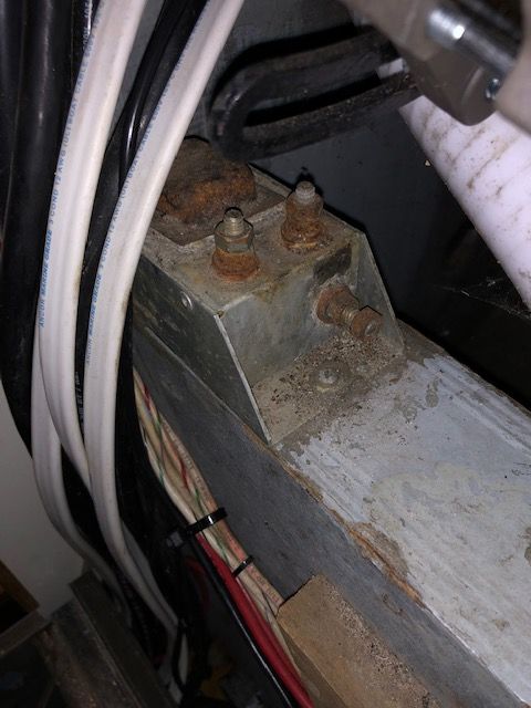
I have no idea what it is exactly, but I was told it was a voltage regulator for the alternator and was no longer needed because the new alternators have internal voltage regulators. Is this an external voltage regulator for the old alternators or is this possibly part of my ignition/engine start problem?
Issue #2: Is there a wiring diagram somewhere or can someone walk me through the wiring from the "On-Stop" switches and the starter push switch to the coil? The starters are working fine, so I don't believe I have any issue between the On-Stop toggle, the push switch, and the starters. However, what is the wiring run from the On-Stop switch to the coil so the ignition continues to get power after the starter has lit the engines? If I've got 12 volts coming off of the On-Stop switch when it's on, where does that wiring/current go to next? Directly to the coil? To a voltage regulator somewhere? If someone could help me fill in the blanks between the On-Stop switch and the coil, there was be very helpful.
It's always something right at the end. Appreciate any help you guys can give me.
Thanks,
JohnV8r
Issue #1:
The only thing I disconnected during the rewire that related to the ignition/engines was this thing:
I have no idea what it is exactly, but I was told it was a voltage regulator for the alternator and was no longer needed because the new alternators have internal voltage regulators. Is this an external voltage regulator for the old alternators or is this possibly part of my ignition/engine start problem?
Issue #2: Is there a wiring diagram somewhere or can someone walk me through the wiring from the "On-Stop" switches and the starter push switch to the coil? The starters are working fine, so I don't believe I have any issue between the On-Stop toggle, the push switch, and the starters. However, what is the wiring run from the On-Stop switch to the coil so the ignition continues to get power after the starter has lit the engines? If I've got 12 volts coming off of the On-Stop switch when it's on, where does that wiring/current go to next? Directly to the coil? To a voltage regulator somewhere? If someone could help me fill in the blanks between the On-Stop switch and the coil, there was be very helpful.
It's always something right at the end. Appreciate any help you guys can give me.
Thanks,
JohnV8r
Bertram 31 - The Best Boat Ever Built
Re: Coil Voltage
I have a 79 28, but I think the wiring should be somewhat similar. On the old point type ignition the coil is supplied from 2 sources: when the starter switch is closed 12 volts flows from one terminal on the starter solenoid to the coil. This supplies a hotter spark to get the engine started, but cannot continue when the engine is running. If you continue to supply 12v the coil will overheat. On my boat this wire from start switch to solenoid is yellow.
Once the starter switch is opened power for the coil is supplied through a resistor which steps the voltage down to about 8 volts. Older engines used an external resistor, which usually looked like a piece of white porcelain about 1/2 inch square by 4 inches long. Later engines used a resistance wire, which is what I have. It looks like a regular wire, but the length and internal resistance is calculated to deliver the reduced voltage to the coil. This is the wire that is connected to the on-stop switch; on my boat it is white, and is connected to the same terminal on the coil as the wire from the solenoid.
If you pm me your email I can send you the diagrams.
-
JohnV8r
- Senior Member
- Posts: 625
- Joined: Jun 29th, '06, 21:59
- Location: Northern California Bay Area
- Contact:
Re: Coil Voltage
Tooeez,
PM sent. Thanks so much for your help!
JohnV8r
PM sent. Thanks so much for your help!
JohnV8r
Bertram 31 - The Best Boat Ever Built
Who is online
Users browsing this forum: Google [Bot] and 438 guests