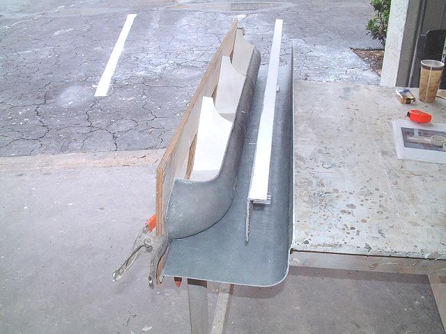
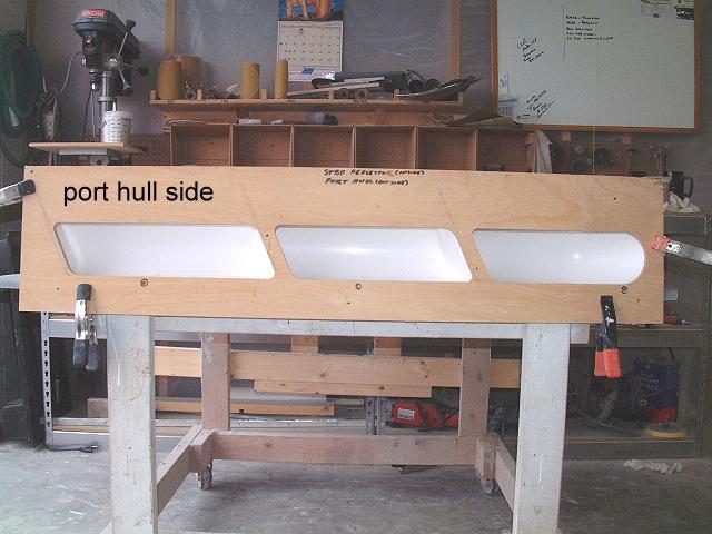
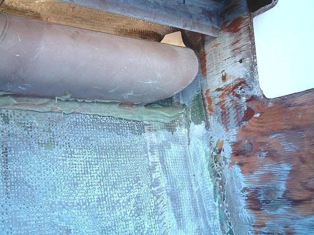
Bertram 31 Side Opening Air BoxesThe original style side induction air system consists of three elements; the primary deflector, the secondary deflector, and the dorade pan. Air enters freely through the opening in the hull side, passes upward past the primary deflector and is drawn down and past the secondary deflector. Any water that might splash up past the primary deflector is blocked by the secondary deflector and drops into the dorade pan to be drained away. Before installation begins, you should first study the system and how it's related to your Bertram 31. Note that certain spacings must be optimized for the best performance. The pictures below will help you understand the dimensional requirements. On the outside of the hull carefully layout the vertical points dictated by the forward engine space bulkhead and the aft engine space partition. This space will be approximately 52" in length. Next note the horizontal line dictated by the underside of the gunnel, where the secondary deflector will be bonded. If plywood exists under the gunnel, it is strongly recommended that you remove it so the the deflector can be epoxied directly to the fiberglass. It may also be necessary to re-locate the fuel fill and the wiring chase on the starboard side. The height of the top lip of the primary deflector should not be closer to the underside of the gunnel than 3 1/2". The secondary deflector and dorade pan have been cut oversized and will need re-sizing to fit your specific boat. The lower lip of the secondary deflector must be a minimum of 1/4" below the upper lip of the primary deflector. Both the secondary deflector and the dorade pan will span the entire length between the forward eng space bulkhead and the aft engine space partition. When all three items are correctly spaced and bonded into place, you will have a relatively dry air delivery of approximately 150 square inches, suitable for a diesel engine up to 350 hp. Once that you have laid out the proper spacing, use the supplied template to mark the three openings to be cut into the hull. Most of the Bertram 31s were fitted with exhaust blowers. The hole for these blowers may be out of alignment with the hole that you will cut for the air system. It will be easier to glass over these holes prior to cutting out your new holes. Cut the new holes very carefully and note that by drilling and screwing the template into place with the holes that match up to the primary deflector, you'll be assured of a good match between the air hole and the deflector. Register and epoxy bond the primary deflector to the inside of the hull. Once the epoxy has hardened, remove the register screws and bond the secondary deflector to the underside of the gunnel. It will be helpful to screw the deflector to the gunnel from the top, again removing the screws after the epoxy has hardened. The final item is to install the dorade pan. It will fit up against the lower flange of the primary deflector and run from bulkhead to partition. Make allowance for your drain, which will be at the aft outboard corner of the pan. You can elect to drain the pan directly overboard via a 1" through hull fitting, into the bilge, or through a through hull fitting below the water line. If you elect to drain below the waterline, you must also use a sea cock that is easily closed off in case your drain tube breaks or comes free. For simplicity and cosmetics, draining directly to the bilge is best. Again, approach this project with careful planning. Pay attention to all spacing requirements.  Kit will contain the following:
Construction of the Air Box is 100% polyester resin and fiberglass. Installation should be done using epoxy resin and Cab-O-Sil. Addition of fiberglass mat or cloth as tabbing is not necessary. The Air Box and hole template have been designed to give optimum free air delivery for any engine up to 300 hp. Acceptable air delivery for engines up to 400 hp. Air delivery is calculated for diesel application, so any size gas engine is more than covered.

For additional information, please contact: Capt Patrick McCrary |
