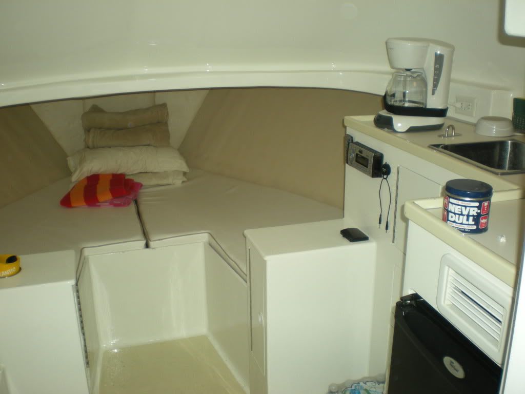
I bought this boat re-done. As i ran it in rough water this summer parts of the interior, where the caninets join the floor and around the corner joints of the cabinets, are starting to crack and chip. Have had a couple of local fiberglass people look and they say its a major undertaking - basically have to redo most of the cabinets. I think the problem is that the cabnetry is faired to the floor (hope this is the right terminology and spelling). I think the original cabinets were attached but free floated with gaps. when this interior was re-done the cabinets were made one with the floor by what looks to be fairing compound (like bondo) and then paint. basically the whole interior is done like this but stress is only evident around the bulkhead between the main cabin and v-bert area - a major flex point of the hull i would assume. Take a look at these pictures and give me some thoughts.
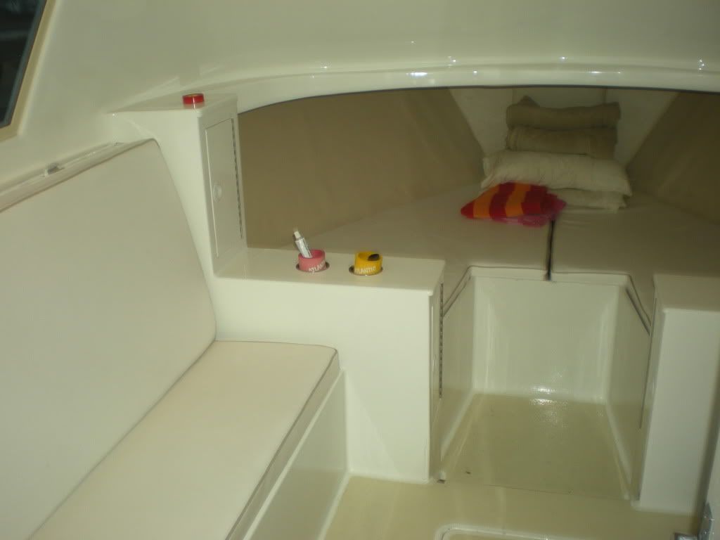
just to give an idea of the structural layout... now the stress cracking...
I agree with you that the redo done the way it was, left no room for hull flexing. I would not have a repair made to have it look the same way, ie: filling, fairing and painting, because in my opinion it would be a set-up for having the same thing happen again. Short of doing what one of our bretheren did on the Phoenix--Rebuild the front cabin/glassed windshield area like an immovable Sherman tank, all of our B-31's flex to a greater or lesser degree. If what was redone was done in wood rather than fiberglass faired to the floor, you wouldn't have noticed a bit.
The redo is pretty, but the advice you were given is correct, it is a major project. My first comments are, you can clearly see that there is no bond between the new finish and the old formica. Second, it appears that there was either not enough glass, or the wrong type on all the curves and radius. Finally, I'm not sure what type of resin was used, but you might want to ask Capt. Patrick what he would have used, and how he would have laid it up.
Generally, in a project of this scope, the entire interior would have been gutted and modern materials such as corecell, coosaboard, divynicell or something along those lines. I like to use Vinylester Resin as it offers the bonding ability of epoxy, but with the flexibility and chemical properties of polyester -- which is what the boat was built out of.
I don't want to scare you, but I think the advice you have been given is sound, and any attempt to patch/quick fix will only result in the same situation down the road.
i wonder if the stressing will stay in the current area or eventually spread thoughout the entire cabin. I had figured i would live with it as long as i could and then gut the cabin section around those cabinets and front bulkhead and build back with a prpper design. it was gutted when it was redone originally, just not a proper design i guess.
Yes, but that's what made it immovable. A sharp flex caused by coming off a wave has nowhere to go except crack at the weakest joint. I have a Sportsfisherman and some winters if she's not blocked up perfectly, midships cabinet doors really stick. In Spring, in the water they're perfect. Before getting into big bucks, you might want to consider doing things in stages. First grind out and separate the faired floor connections. Then cosmetically just fill the cracks that show the worst. They are the points where you had the most stress. Don't paint yet. Use the boat for half (or more) of a season to see if those points open up again. If they don't, you've relieved the stress points and you can feel more comfortable about painting/touching up.
the pictures look a little worse than it really is. i think (hope) its just a matter of the cabinets being faired and painted to the floor when the hull flexes.
If its brown formica on the bottom then its original manufacture.... plain and simple. No body redoes a boat and formicas before finishing. The fact that the cracking is forward of the bulkhead isn't a bad thing. This is where the boat comes loose fisrt.
Check the tabbing on the hull at those locations forward of the step down and make sure it is still adhereing. There is an awful lot of putty work that took place to get the cabin floor that nice, if you are only breaking loose on that step it could be repairable, the movement is coming from the bulkhead have a look and report back.
These 31's are a great hull, but there is allot of twist that occurs in them, espcecially when you take out significant portions of the forward bulkhead to open the intieror up. Its not a safety issue as far as it is a cosmetic issue. That boat has had a signifiacant power upgrade and if the bulkheads haven't been supported to handle it you will see twist and flex occur through the boat, the most overlooked section is the bow (known from experience)
None of the brown formica covered ply was originally tabbed to anything, it was meant to flex. Bonding it is no good.
The hull will flex a good bit, mostly forward of the engines. Remember, the boat has a "self supporting hull", i.e. no transverse stringer system at all. Only has the engine stringers and those are just for the eingies to sit on. But in spite of all that, its still a pretty stiff hull fore & aft, just twists on its longitudal axis forward of the engine area.
i will try to get some pictures of the forward bulkhead from under the floor. had someone look a couple of days ago and from the aft side, the forward bulkhead appeared to be intact where it joins the hull. will look better in a few days and report back. Thanks BB
Wlbsr,
I have never been a fan of opening up the forward FRP dash/hanging locker area, like Walter, UV & JD said these boats were originally designed to flex.The area was intended to be a partial floating bulkhead. This area was originally part of the molded cap that is part of the entire forward deck. It was fastened with screws at the top, tabbed with FRP at the outer hull edges and bottoms and had fairly open joints designed to twist and turn with the boats motion and sea conditions. The opening was only about 24" wide not 8' of unsupported bulkhead it is now. The sole area between the V berth was originally a 8" step down not raised like it is and had wide open joints in the floor boards to allow for twisting of the bow.
I agree with Walter clean out the damaged cracked areas, cut back the filled and radiused bondo joints. Smooth out and fill with paintable life caulk or silcon. As for the peeling fairing over the original brown formica, grind it down to get good adhesion and re-shoot to match the paint, but leave an open joint for flexing.
Did this damage happen on one wave or over a period of time and how big was the sea conditons and what speed were you running when it happened. Don't get in panic, it's mostly cosmetic but is a pain to have to fix, especially when you just got the boat.
You might want to check under the V-berths I bet the plywood joints under there are also cracked. Take your time with the repairs and listen to the advise from the board members, we have all been through some sort of problems with our boats.
Pete Fallon Marine Surveyor AMS SAMS
Wlbsr,
In my previous post I said that the sole between the V berths was raised, I take that back after looking at the pictures again you do have a step down. The long crack is the very top of the partial bulkhead that runs across the boat, tabbed into the bottom and hull sides. A quick fix for that area would be a recessed threshold or a trim peice either out of stainless or teak. Just a thought and a correction from my last post.
The long crack is the very top of the partial bulkhead that runs across the boat
thanks for your expertise Pete, this long crack is purely cosmetic. it looks like a piece of 1/4 "something" was stuck to the fore side of the step-downand painted with the floor and is now starting to pull away at the top but the sides are secure. I thought i could make a clean cut here and caulk for now.
i will look at the front of the bulkhead and under the births in the next day or two.
my thoughts on a temporary repair on the cabinets would be to screw the sides down to the deck from the inside (they probably already are) and then cut a gap around the bottoms. caulk and paint the gap allowing it to expand rather than making a seemless connection with the floor. i think this is what you are saying also.
i think it was more "one day" than "one wave" that several cracks appeared, but it has mostly been gradual thoughout the summer. it was 3-5 in a head sea... something that i will run in a couple of times a year at the most. i haven't really pulled any punches running this boat, maybe i should. Thanks again. BB
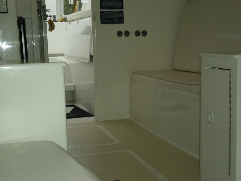
agree with my brothers " something gotta give" when i did my interior ,i removed those ugly bolts holding the deck cap to the bulkhead under the windshield, next i taped the outside joint real good and went i the inside and filled with thicken expoxy .when slightly tacky i used a mirror in the hanging locker and tabed with two layers of woven-roving and episize tape.the cabinet on the starboard was easy because the main electrical pannel swings down into v-berth. the flex joint become the original seam were the cabinets meet the floor. so i agree with pete you need a flex joint there. this year we use the sat phone due to the close (33miles) range of tuna. so we race out there on a moments notice slamming waves at 28 knt. i don`t have so much a a paint crack .here is the same area were cabinet/step to v-berth are.
This is defiantly an example of a learning process for anyone who is anticipating major interior modifications...
There are a number of things to be learned here, starting with overall strengthening of the cabin itself. The stock B31 cabin was constructed on a rather loosely assembled group of fiberglass, plywood and lumber components that more or less floated within a fiberglass shell.
The main ways to avoid the problems depicted here is by either using the original component techniques that Bertram used or, if the desired look of the interior is to be more modern and molded in, the overall cabin shell has to be beefed up considerably and made much more rigid.
To accomplish this the following items must be addressed:
Pilasters: outside panels glassed, changing the nature of the pilasters from a channel structure to a box structure. The stock bolt configuration of the pilaster to hull cap has to be changed to a fully glassed configuration making the pilasters integral to the hull cap.
Aft Cabin Bulkhead: Increased in thickness from 1/2" to 1" or more. The bulkhead has to be epoxied and screwed into place so that it also becomes an integral element of the superstructure.
Front Window: If the stock front windows are to be kept, the whole frame should be removed and re-installed with new bedding and hardware, especially the 3 all thread rods between the hull cap and the house top. These were originally done with aluminum rods and secured with stainless nuts and washers. Change over to stainless rods. The original aluminum rods are often already broken due to dissimilar metal corrosion...
I prefer, for numerous reasons, to totally replace the aluminum windshield frames with a composite sandwiched one piece replacement. Like the aft bulkhead, the composite replacement unit must be epoxied and screwed into place, making it also an integral unit with the hull cap and house top. Side windows play yet another part in strengthening the cabin. By making them fixed with tempered glass, either by glassing in reveals and glazing the glass in or by installing fully welded aluminum frames, glazed with tempered glass. (American Marine Style)
Following these recommendations, the whole cabin becomes a monocoque structure, still capable of handling flexural forces, but greatly limited from that of the original Bertram design.
Cabin Appointments:
Subdeck: However you decide to finish the cabin sole, the first element needs to be a substantial subdeck. This should be a minimum of 1/2" and well secured to the stringers. I used 3/4" plywood for the subdeck on Hancock's Boat and 1/2" on Buddy Boy.
Cabinetry: All cabinetry, regardless of design, must be secured to the subdeck and other attachment points in such a way as to allow it to somewhat float at these attachment points. Do not use any fairing compounds to hide joints. If necessary to hide a joints, use strips of solid wood that hide but accent the joint.
Another point of consideration, having nothing to do with construction techniques, is that of proper boat handling.
Keeping in mind that anything that man can build, Mother Nature can destroy, drive your boat according to environmental conditions. The rougher the sea conditions are, the more destruction of man made structures will be evidenced if you continue to run the boat like it was a calm summer day on a lake.
Slow Down as the sea conditions worsen... It'll save you and your crew a lot of physical anguish and be less likely to break the boat and your pocketbook.
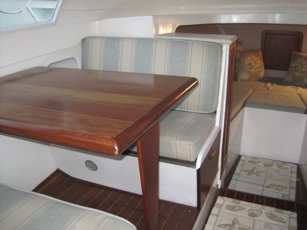
I think if this boat had a floor similar to yours he would not have a problem, it seems the weak link was faring everything to the deck.
However, when you see some methods used in one area you have to wonder about those used in other areas as well
capt patrick there is one other condition you did not mention. a human one ,that is a tension headache and it comes from starring at the water knowing damm well the boat is going to hit a set of waves that will launch the boat so you are constantly ready to take evasive action .that will cause a migrain headache . the problem is you don`t get there while the " bite is on ----don`t bother" for rookies like me it is the only way. i feel it is still better then going at a slower speed in total darkness .
as a stop gap measure, would you attempt to recreate a joint between the cabinets and the floor? that just seems to be something that might not be too much trouble. other than that i plan to look at it for a season or two and see what happens. thanks for your input.
Maybe get yourself a Roto zip type tool and us a straight edge to cut some seams in the fairing. You can then tape beside and carefully caulk the seams. They probably won't be too noticeable if they are straight.
not hard at all . purchase a cheaper version of a vibrating FEIN tool made by at least three of the leading manufacturers. using the floor as a guide make a cut and fill in with some kind off flexiable cauk . i am sure robbie at raybo marine has a sugestion he deals with interiors on a everyday basis . capt. patrick is a pro with our beloved 31 bertram between them you have the best of the best.
I see you're in Morhead City. I've used a guy named Will Harding at Carolina Yachts. He has a shop in Beaufort. He's done some work on my boat. I thought his prices were fair. You may work to give him a call 725 3819. Buzz
what is the tool i have seen people using installing a laminate or tile floor. they use it to cut out door molding so they can slide the laminate or tile under it and don't have to cut around it.
that is it, thats the tool .check out amazon.com go to rockwell,craftman . i belive fein tool co was the first on the block that is the one i have used.called fein multimaster .
The Dremel is the one I have. I opted for the lowest priced manufacture simply because I rarely use the tool. Life expectancy to the tune of $200+ extra wasn't that important...
just looked at it again. these cabinets are not sitting on top of the floor. looks like both sides (walls) of both cabinets are 1/2 plywood and go all the way down and are tabbed to the hull and partially to the stringers where they cross. there is no sign of any stress where they meet the hull or stringers. the cabinet sides were either original or , if not, def. there before this redo. it looks like 2 sides of the new cabinets were built around the old cabinets maybe to cover an opening for a previous electric panel or possibly an A/C. i am wondering if part of this cracking may be the new outer cabnet sides shifting around the original walls. it looks like the tops or the original cabinets were cut off to lower them. there is not a lot of cross support so i am also wondering if the cabinet sides may be moving relative to each other above the floor line but not necessarily in relation to the floor.
i forgot my camera but i will get some pictures to clarify in a day or two.
I have the cheap Harbor Freight. I use it all the time cutting stuff. It got a real workout when I was removing the deck and supports from Doc's old 31B Happy Hour. The HF took a licking and kept on ticking. It also works great on grout, drywall, fiberglass. I got it to remove bottom paint. Does not work for that very well.
I wonder if the formica under the faring is moving or expanding at a different rate than the floor? Unfortunately the whole surface is only as strong as the adhesive attaching the formica.
Not that I am an expert as Capt Pat is, but I would believe that Formica would be a very poor material to try and get bondo to “Stick†to. Not only are you expecting the 30 year old contact cement to hold, but Formica is a very smooth surface for bondo to adhere to. No offence to the people that did the work, but when I did my interior, I cut all the old material out except the tabbed portion below the deck and screwed/5200 new ¾ furniture ply impregnated with resin, kitty hair to flare, then layer of roving, then mat, finally a little skim coat of bondo to make a smooth surface for the gel coat. I hope that I don’t have the same issues, only time will tell.
my uneducated opinion now is that it is the box itself moving either old panels against new panels or the whole thing flexing with the floor staying stationary. it almost seems easier to beef up the whole box from the inside so it can't flex and twist and then try to beef up where the box is secured. you would have to start all over again to try to make the cabinets independent of the floor and hull - doesn't look possible just to cut the fairing back out to create an expansion joint. just don't know if it is possible to beef everything up enough around and inside what i already have. the main problem is that it will be trial and error and hard not to spend a decent amount of money without any guarantees. i may go in on the front side (maybe below the stepdown) and try to cut out some of the fairing compound to try to get a feel for what that joint looks like.
isn't it somewhat standard to fair the cockpit deck to the sides? i guess the deck is a lot more substantial back there, the engines are keeping the hull stiff, and its not really a point of impact?
did you have two bulkheads of 1/2 or maybe 3/4 plywood about 12 or 16 inches apart making up either side of the cabinet that went all the way down and was tabbed into the deck. and did you cut this off at the deck level and then build the cabinets back sitting on top of the deck? Bill
I completely gutted the whole interior, however I left a portion of the original forward bulkhead that was glassed to the hull and cut it off below the deck level. I figured the tabbing looked great and there was no sense in removing it. I used it as a “foundation†for all the new pieces. The floor is 5200 and screwed to the stingers, but is not glassed to the vertical sections. I am going to use a teak and holly floor, not make it integral to the vertical pieces as your vessel is. However in a couple places it is attached with a 1x1 ledger on the bottom and then glassed as I stated before. However I have not used anything but fresh ply to glass to. In fact there is almost nothing left of the brown Formica but the rear bulkhead and the forward bulkhead below the floor level. I also do not have a step down, the floor is all at the same level. Although not complete, yes very big job, I could send you pictures, but I am not the expert that Capt Pat is. If he gives advice, I would take it in a second. I have tons of glass/construction experience, but I only have 1 Bertram 31 to screw around with.
i am not a DIYer. just need to educate myself to be able to proceed with a professional for stopgap measures for now. not too worried about it now unless it starts to show up everywhere and it is isolated to this forward bulkhead after a year now. put a picture or two up here if its not too much trouble. thanks for your comments.
agreed. the guy that has done some electrical work for me is really on me. started going over last year and will probably get another big chunk done this winter.